Designing a commercial drop ceiling requires a strategic balance between structural integrity, aesthetics, and localized building codes. A well-engineered layout goes far beyond simply dropping tiles into a grid. Whether you are dealing with high-humidity zones or high-risk seismic regions, following a precise, professional engineering workflow is critical.
Here is the step-by-step framework on how to design t bar ceiling systems that meet strict industrial standards.
Step 1: Analyze Spatial Constraints and Environmental Loads
Before drawing any grid lines, you must evaluate the specific environmental factors of the project site. The material selection of your grid relies heavily on this step:
Moisture Levels: For standard office spaces, standard electro-galvanized grids suffice. However, for commercial kitchens, pools, or labs, you must pivot to a heavy-duty waterproof or aluminum system.
Weight Load Categories: Calculate the combined dead load of the acoustic panels, insulation blankets, and integrated mechanical services (HVAC diffusers, light fixtures). Main runners must be rated as Light-Duty (5–7 lbs/LF), Intermediate-Duty (12 lbs/LF), or Heavy-Duty (16 lbs/LF) based on ASTM C635.
Seismic Zones: Determine the Seismic Design Category (SDC A–F). High-risk zones (Category C-F) require specific structural bracing and perimeter clips.
Step 2: Establish the Grid Module and Balancing the Perimeter
A common mistake in learning how to design t bar ceiling layouts is failing to balance the room, resulting in tiny, ugly slivers of tile at the walls.
Select the Module Size: The most standard global commercial sizes are the 600x600mm (2'x2') matrix or the 600x1200mm (2'x4') matrix.
Calculate Balanced Borders: Measure the total room length and divide it by the length of a single tile. Take the remaining fractional dimension, add the length of one full tile, and divide by two. This gives you the exact, uniform width for the border tiles on opposing walls, ensuring a symmetrical, visually centered installation. Always aim for border tiles to be at least half the width of a full tile.
Step 3: Map Main Runner Placement and Hanger Wire Intervals
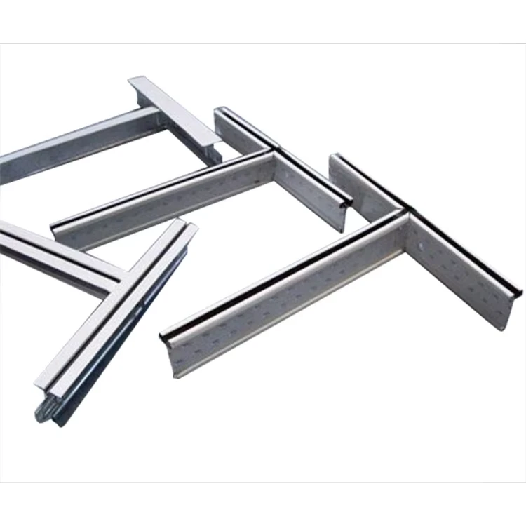
The structural backbone of the entire ceiling depends on the layout of the Main Runners.
Primary Spacing: Space the Main Runners exactly 1200mm (4 feet) apart, running parallel to the longest wall structure.
Suspension Points: Hanger wires (typically 12-gauge galvanized wire) must be securely anchored to the structural deck above and attached to the Main Runners at maximum 1200mm (4-foot) intervals.
Pro Tip: The first suspension wire must be installed within 450mm (18 inches) of the perimeter wall to prevent edge sagging.
Step 4: Integrate Cross Tees for Torsional Stiffness
Once the Main Runners are suspended and leveled, Cross Tees are inserted to form the final module cavities:
For a 600x1200mm system, insert 1200mm Cross Tees perpendicular to the Main Runners at 600mm intervals.
For a 600x600mm system, field-install an additional 600mm Cross Tee to bisect the 1200mm modules.
Ensure the interlocking tabs engage with an audible click, validating that the system has achieved its rated torsional stiffness.
Step 5: Incorporate Seismic and Localized Code Compliance
If your project is located in an earthquake-prone region, mastering how to design t bar ceiling arrays means implementing strict dynamic separation:
Perimeter Flanges: Use an oversized wall angle (minimum 50mm flange width).
The 2-Wall Rule: Fix the grid rigidly to two adjacent walls, but allow the opposing two walls to float freely using seismic separation clips with a 20mm clearance. This allows the building envelope to sway without crushing or collapsing the ceiling plane.
Rigid Bracing: Install compression posts and 4-way diagonal splay wires every 12 feet to neutralize lateral forces.